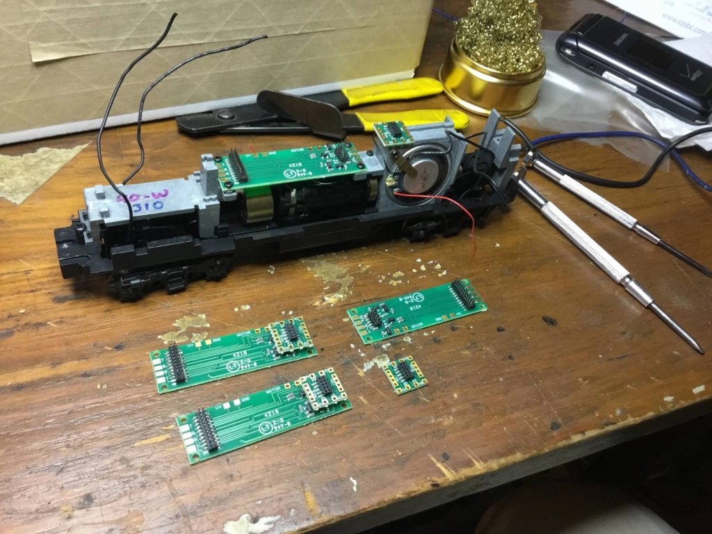
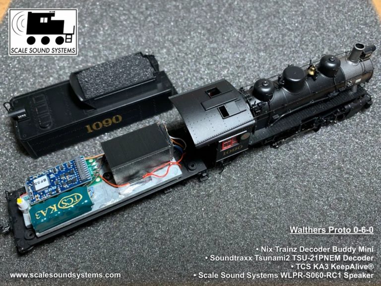
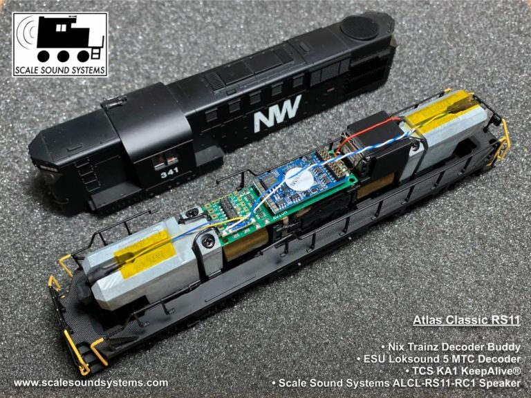
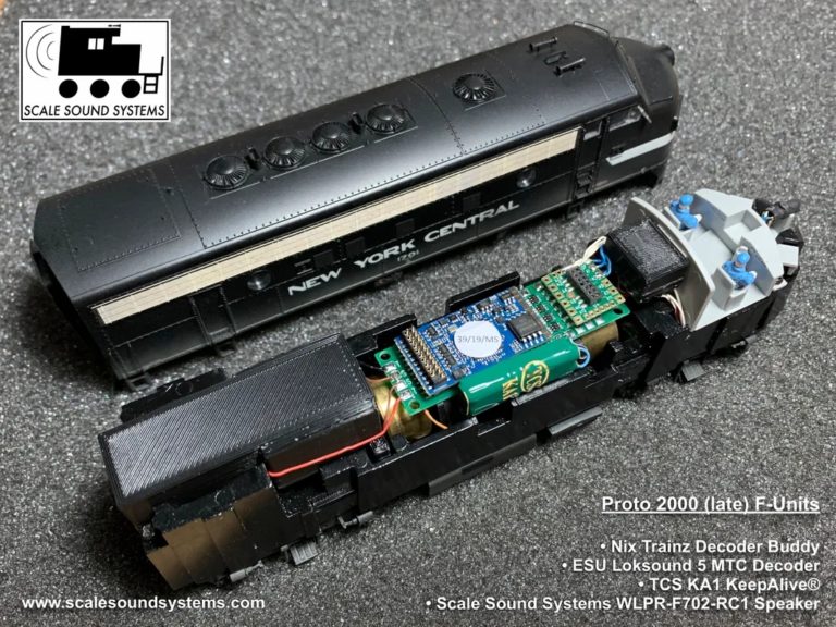
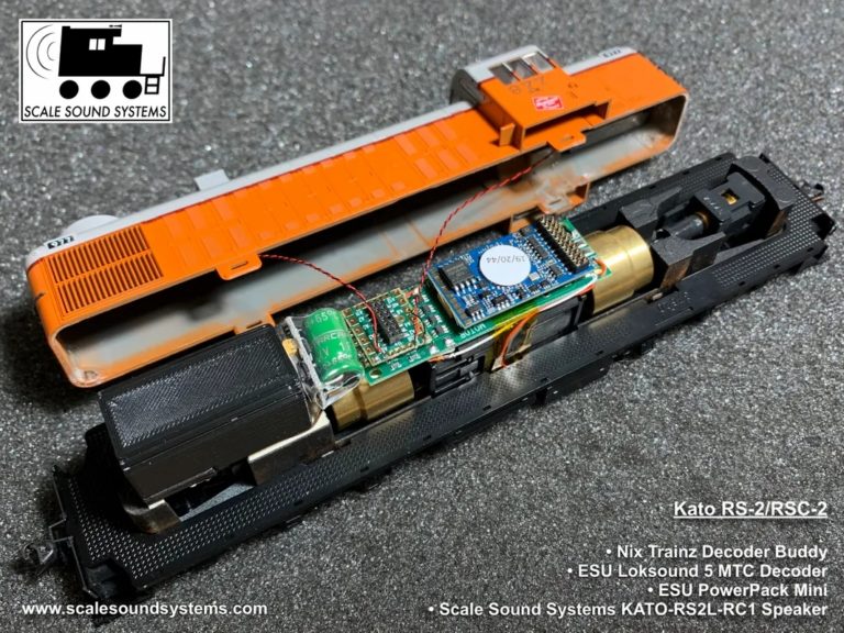
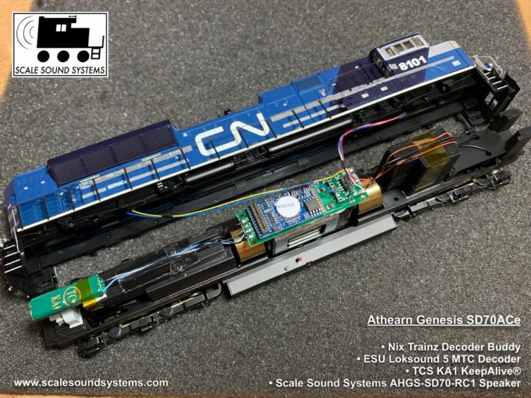
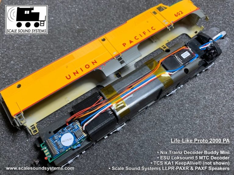
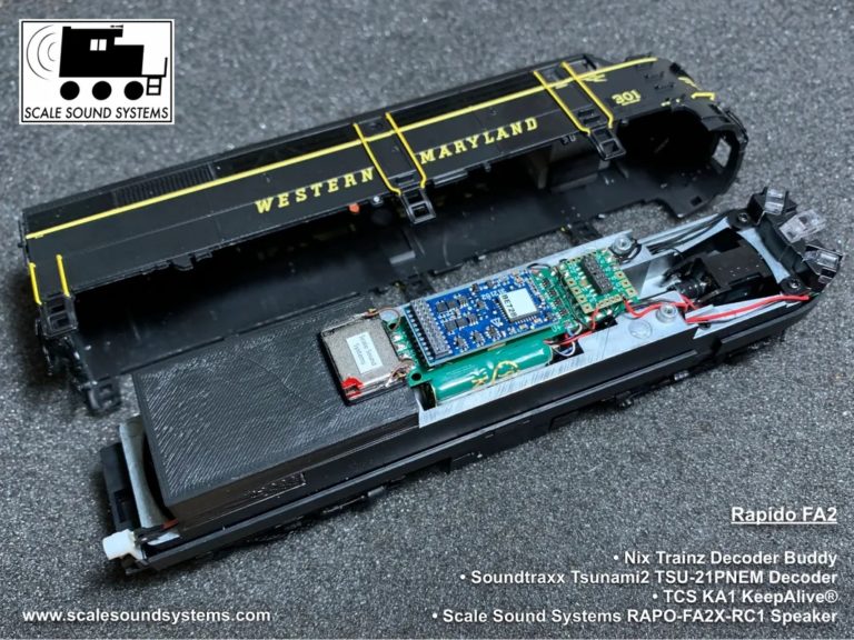
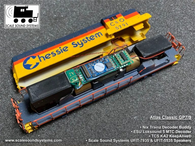
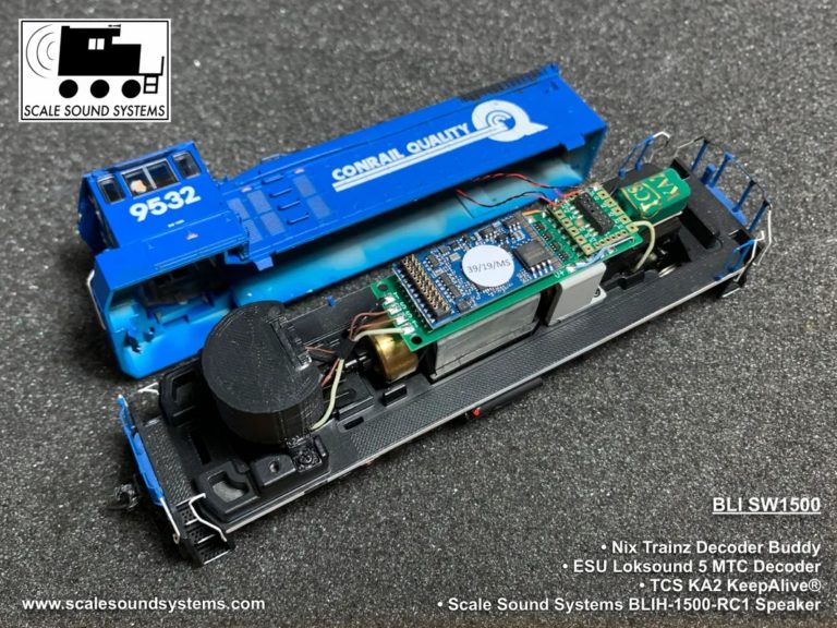
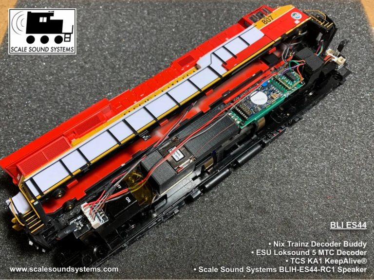
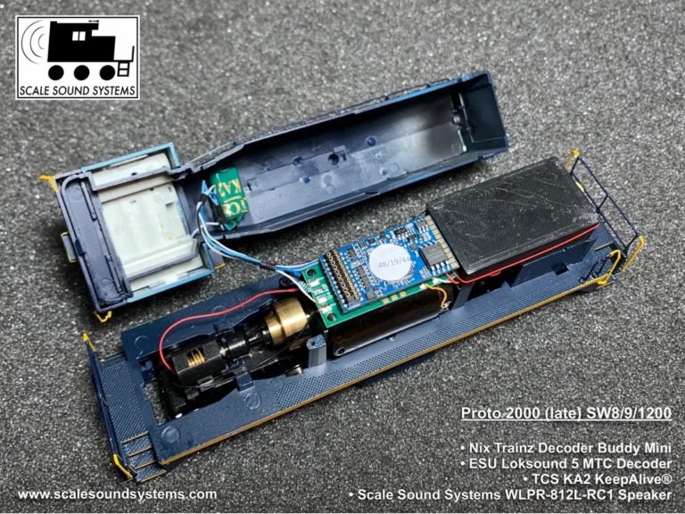
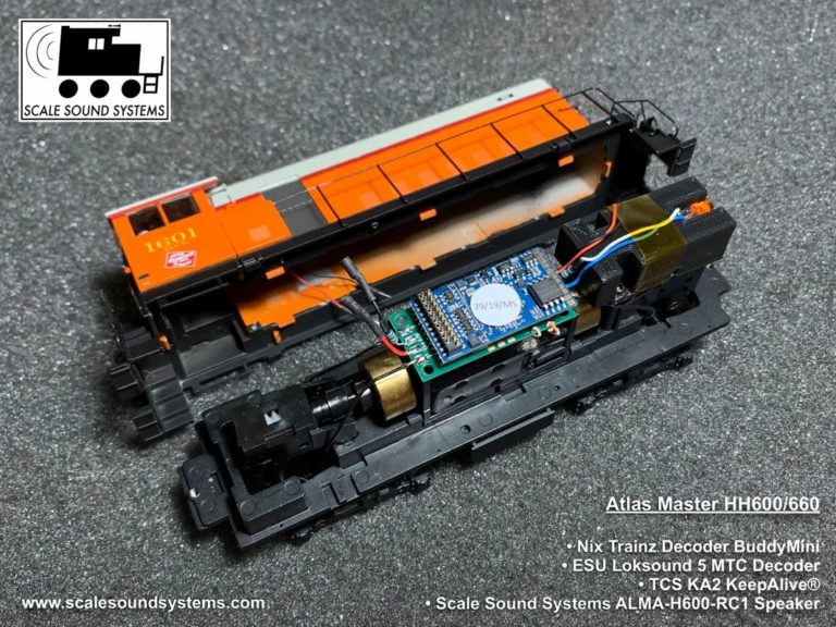
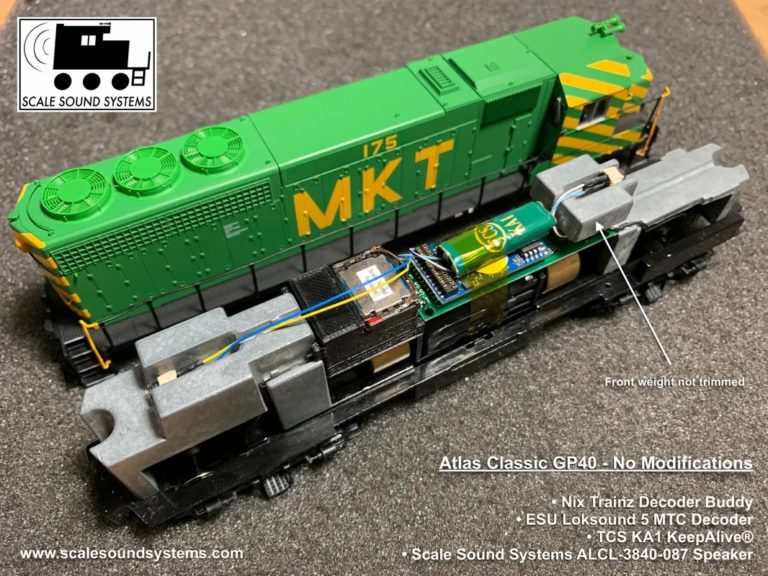
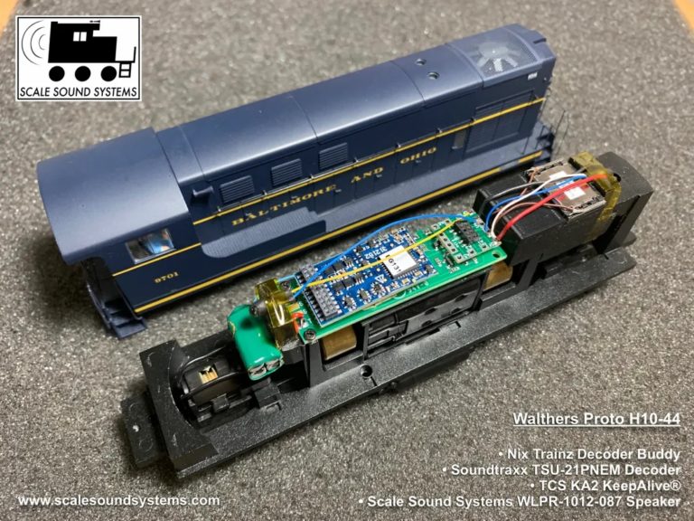
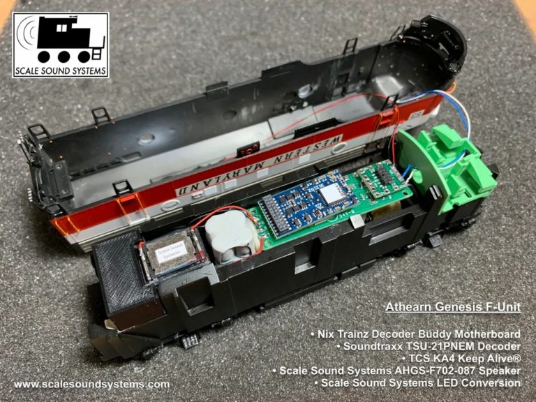
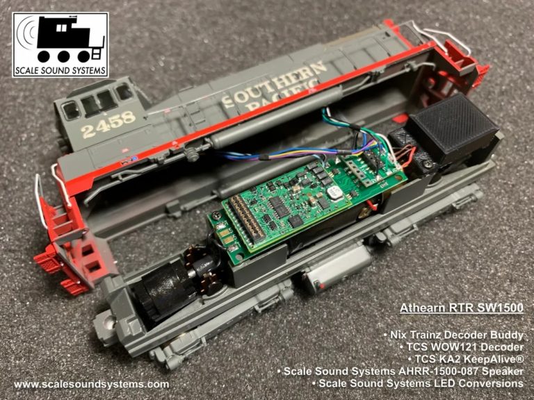
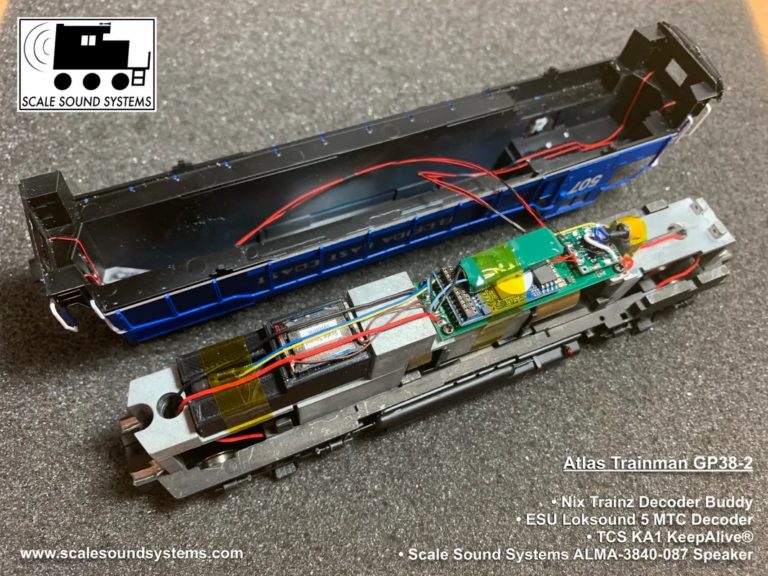
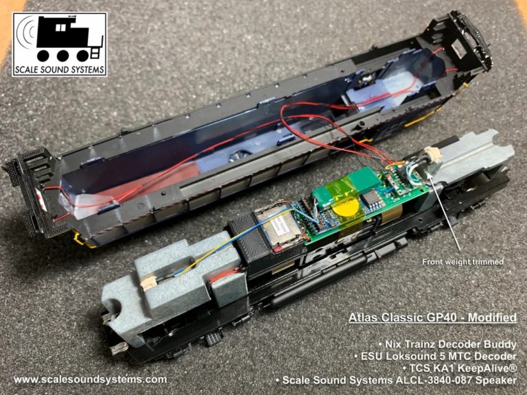
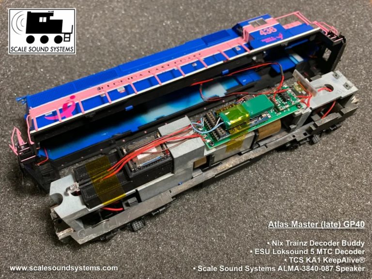
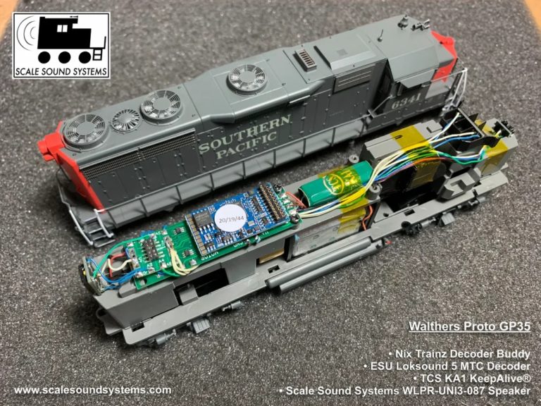
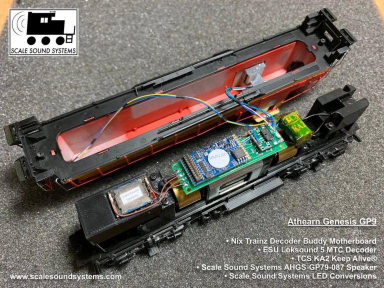
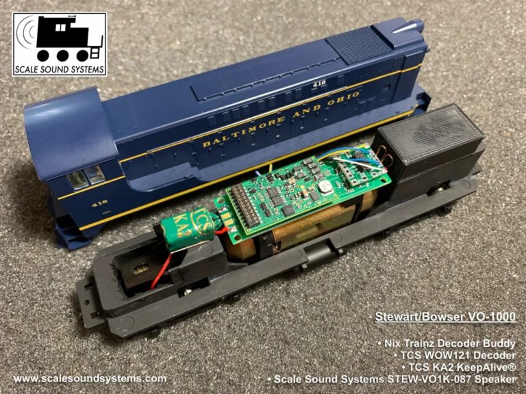
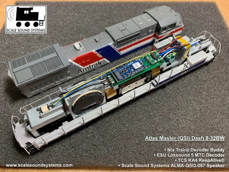
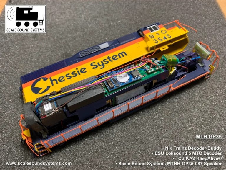
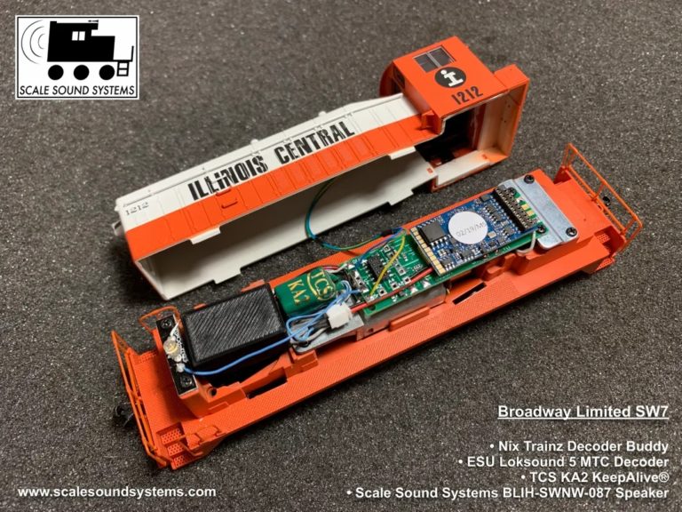
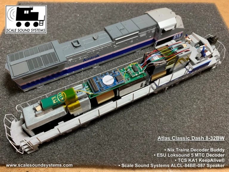
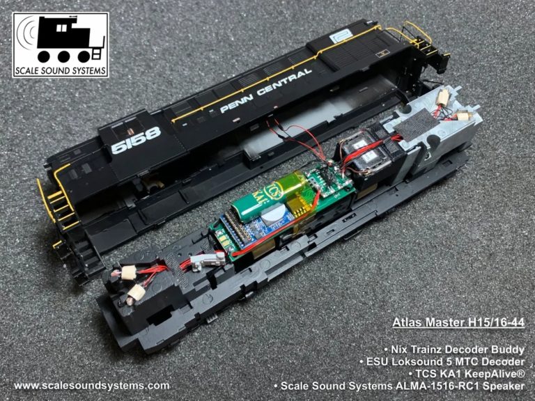
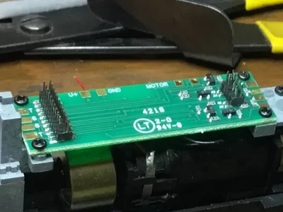
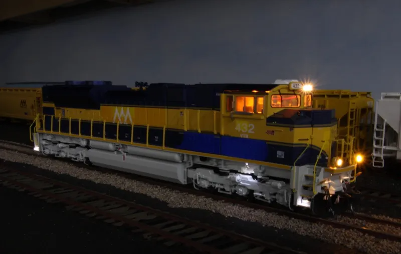
Installation Pictures by JT Burke

Metric Machine Screws for Atlas Locomotives
The four screws used to hold the Decoder Buddy onto the weights of Atlas locomotives are 1.6 mm x 4 mm metric machine screws. They are fairly common and found on both Amazon and eBay. These are the ones I purchased:
Find it on Amazon
Participating Dealers and Installers
Bob The Train Guy bobthetrainguy.com
BradleyDCC Custom Models bradleydcc.com
Credit Valley Railway Company Ltd cvrco.ca
Custom Sound Installations (301)-990-6126, Fly3789@msn.com
House of Trains houseoftrains.com
EngineHouse Services, LLC enginehouseservices.com
Litchfield Station litchfieldstation.com
RailMaster Hobbies Inc railmasterhobbies.com
Scale Sound Systems scalesoundsystems.com/product-page/nix-trains-decoder-buddy-motherboard
Squeaky’s Trains & Things LLC squeakystrains.com
Streamlined Backshop store.sbs4dcc.com
Tony’s Train xChange tonystrains.com
Yankee Dabbler yankeedabbler.com/nixtrainz-decoder-buddy-motherboard-for-21-pin-decoders-scale-ho-nix-decoderbuddy
Yankee Dabbler West
Look For Decoder Buddys At Your Local Hobby Shop!
Videos of Interest
Larry Linger “Solo Contracting” on YouTube has a large number of installation videos that are very well done. He uses Decoder Buddys in a lot of his installations and has great soldering techniques and also demonstrates good problem solving skills. I recommend that you search Solo Contracting on YouTube and see if he is doing your locomotive or just plain watch him in action. He is an excellent teacher by word and example!!! Here’s a link to one of Larry’s videos to get you started. https://youtu.be/JKYTWCv_mRQ
J T Burke at Scale Sound Systems put this video together to show off the original 8 output Decoder Buddy’s lighting functions in action. His speakers are worth looking into. They are very fine! https://youtu.be/vKD_KfzgKhs
To visit Nick’s personal YouTube Page click here: https://www.youtube.com/@nicksanto882
Bulbs on DCC Decoders
This applies to both OEM and Miniatronics Aftermarket Bulbs
This morning I went to the parts cabinets and rounded up some resistors and Miniatronics 15 ma bulbs and some 1/4 watt axial resistors. I used my DC power supply set to 12 volts. I don’t like big surprises.
I found that by experimentation the power for a pair of Miniatronics bulbs in parallel was enough to make me want to let go of the 90 Ohm resistor quickly. A lot of heat. A small surprise. The heat generated by a single bulb through a 180 Ohm resistor was quite warm and I was barely able to hold onto the resistor. The resistor size was chosen by light intensity.
By experimentation and burning up a few Miniatronics 15 ma bulbs I have the right resistor values again. I’m not sure the power requirements of the bulbs are in order with what the smd resistors on the Decoder Buddy will bear. The onboard resistors are rated at 0.1 watt and the power required by the lamp is 0.18 watt, almost twice that.
This leads me to believe that if you want to continue with bulbs you should stay with any inline resistors you are using IF the Original power source is 12 volts. (It may be greater than 12 volts and should be measured to be sure.). The cooler of the two methods seems to be two separate 180 Ohm resistors with a bulb on each resistor. As for the DCC decoder or Decoder Buddy it might be best to use “0” Ohm resistors on the decoder Buddy and axial 1/2 watt resistors out in the locomotive away from the decoder and printed circuit boards AND maybe bonded to the frame of the locomotive as a heat sink. A single light bulb or two in a locomotive with the resistor away from anything plastic might be a reasonable thought, but any more than that I believe is asking for problems.
I had a chat with a person who is more able to offer an alternative with less heat. No solution. I also Googled “DCC decoders and light bulbs” and found no good solutions there.
The other alternative is LEDs. They are very good, long lasting, cool running, decoder friendly and not hard to install. The colors can be believable. I have LEDs in all my sound installations.
I wish I had better news. Maybe I saved you some time and expense. Really consider LEDs. There are a lot of ways to do good lenses and get good long lasting light.
Different resistances for LEDs, bulbs and lamps
Considering the Resistance
Options for Required Resistances On the Decoder Buddy
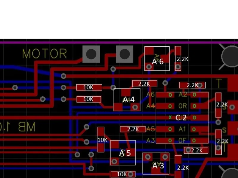
The original Decoder Buddy was designed for use with LEDs. The LED current is set for about 6 ma, Some applications require a different resistance on a particular or all the function outputs for a specific voltage and minimum current. Lamps or bulbs are a good example. Some lamps or bulbs require about 1.5 volts and a little more current than the LEDs. Other lamps or bulbs can handle the full 12 volts to 14 volts provided by the decoder. Still others may have resistors installed inline already and just need the 12 – 14 volts provided by the decoder. I have heard of mixed applications of LEDs and bulbs as well! Some decoders can also provide the different voltages requiring you to choose the appropriate decoder voltage or Decoder Buddy.
There are a couple of ways of dealing with these requirements on the decoder Buddy.
I now offer a Decoder Buddy using 0 Ohm resistors that allow for the full 12 – 14 volt output of the decoder to the function outputs.* Alternatively, for the 12 – 14 volt applications you can also remove the 2.2K resistors easily by placing a hot soldering iron next to the longitudinal axis, melt the solder and flick the resistor away. This leaves two vacant solder pads. You can solder a short piece of ca 24 gauge solid copper wire across the gap, the two pads that can be bridged with solder or you can solder a 0 ohm 0603 resistor onto the two vacant pads.
I offer a Decoder Buddy using “0” Ohm resistors that are more compatible with the 1.5 volt bulbs now also.* A posibility for the 1.5 volt and other bulb applications is that you can remove the 1/2 resistors from your current light board and place them inline. Care must be taken for the heat generated by the resistor. I do recommend conversion to LEDs as a much better alternative.
If you want to purchase the 0 ohm or the 750 ohm types, have a special need for resistance or for a particular configuration feel free to email your request or questions. The price list and shipping costs are the same for the 0 ohm and the 750 ohm Decoder Buddys. Other requests will be on a quotation basis.
The order form is not as versatile as I would like but it’s money in our pockets…. Thanks for bearing with me.
* Due to the number and types of 21-pin decoders that are compatible with the Decoder Buddy and the current draw of different lamps and bulbs, I leave the determination of current loading of the decoder to you to calculate. Do not exceed the current capacity of the discrete function output or the total output of the decoder
Tips And Tricks

Reflow soldering for pads
Reflow soldering the motherboard and the wire leads is a good way to make a good solder joint. I use a good quality solder and fine tipped soldering iron. Heat the pad with the soldering iron and melt a small spot of solder on to the pad. Tin the end of the wire with the solder. Now you have a hand for the soldering iron and a hand to hold the wire. Place the wire on the tinned pad and heat the solder until it melts. Remove the soldering iron and allow the joint to cool. If you don’t feel confident with this procedure find an old printed circuit board and practice removing components and solder wire to the newly vacated pads.
For the first time installation
Some further thoughts
There are plenty of decoder installation videos on YouTube as well as magazine articles to give you ideas about ”how to .” You might also find one that is specific to disassembly of your particular locomotive. The only difference between Decoder Buddy and an 8 pad decoder is the size and the 21-pin Decoder fits into the 21 pin plug.
The large motherboard is one sided but to be conservative a piece of insulating (Kapton preferred) tape placed on the bottom of the Decoder Buddy before mounting if directly onto a metal surface is highly recommended. When mounting with double sided foam tape the extra insulating tape is not required. Electrical isolation of the electronics and the locomotive chassis is the goal.
I prefer to cut the connectors off any of the wires from the track, motor, speakers, lights or stay alive noting any polarities that are relevant. I cut the wires close to the connectors to leave as much wire as I can for routing purposes. Before I solder the wires onto the Decoder Buddy pads I cut them so that there is about ¼” extra. An exception is the motor wire. I prefer to leave it long and tuck it out of the way if possible. The extra ¼” of wire keeps the installation neat and leaves a little play for contraction, routing or whoopses. I also keep the leftover wire for later use. It does come in handy!
Motor wires, motor wire colors and decoder boards have given me fits and wrong way starts more than once. Now I solder the track wires and speaker wires to the Decoder Buddy but only clamp the motor wires to the decoder buddy. I test the direction on a program track to make sure the locomotive moves in the direction that I want it to. If I need to change the direction of the motor I change the leads on the pads and then solder them onto the board.
There are four common ways to install the mother board. If you are lucky you have tapped holes for screws. The screws are most likely metric size (M3?). Second, if you have a circuit board in place that has four tabs with soldering pads on both ends remove it. If there is enough headroom (height) Scotch 2 sided tape works well to attach the Decoder Buddy. The plastic clip should act as insulation if you want to use Kapton tape to secure the Decoder Buddy Directly to the plastic. A third way is to use GOO, rubber cement or silicone gasket sealant as a semi permanent adhesive. The fourth way would be a DC powered locomotive like an Athearn blue box or a Proto 1000 without a printed circuit board. After you isolate the motor electrically you can place a piece of Kapton tape on the bottom of the Decoder Buddy for “isolation insurance” then use the Kapton tape to attach it to the motor.
Read articles, blogs and posts. Model Railroad Hobbyist Magazine and https://model-railroad-hobbyist.com/recent-posts and it’s associated search box in the upper right hand corner have a wealth of information on upgrading locomotives. You should find the price is right too!!!