
Installation
Basic Installation
Tools Required:
- Soldering iron 15 Watt range
- Solder and flux
- Cutting pliers & pliers
- #1 Phillips screw driver
- #2 Phillips screw driver to remove the weights from the frame
- Wire stripper
- Tweezers
Checklist Procedure:
- Remove the shell of the locomotive
- De-solder or cut wires from printed circuit board
- Track wires (2 or more)
- Speaker wires (2)
- Motor wires (2)
- Light wires
- Stay alive wires (2)
- it is important to label (or measure) polarity
- Remove printed circuit board
- Attach the Decoder Buddy motherboard to the chassis, frame weights or motor.
- Solder Track wires (2 or more)
- Speaker wires (2)
- Motor wires (2), (test the direction of the motor before soldering)
- Stay alive wires (2) to the correct polarity terminals (U+ and GND) if desired
- LED light wires to the connector board
- Attach the connector board to the motherboard
- Test the installation before firmly attaching the shell.
Enjoy your newly updated locomotive!!!
Additional V1 Motherboard Information
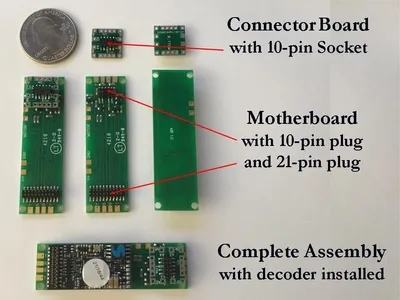
The mother board and the connector board are easier to see in this expanded view (above).
On the motherboard the four pads arranged vertically on each end are, from top to bottom, Track, Speaker, Speaker, Track. The Speaker pads are wired in parallel, top to top and bottom to bottom. The four labeled pads across the top are U+ {a nominal 14 volts and the place where the stay alive blue (+) wire is attached,} GND is ground for the stay alive and two MOTOR connections (Orange on the left and Gray on the right). The two motor pads have through holes in the center to allow for wire insertion from the bottom of the printed circuit board for a neater connection. A consistent motor connection color scheme does not seem to exist so these two pads are not labeled as to polarity or color. You should test that the locomotive runs in the correct direction before reinstalling the shell. U+ and GND are provided for a stay alive. The NMRA Standards state that the positive pin (U+) of the 21 pin decoder should be connected to the blue wire (+) of the capacitor (stay alive). The 21 pin connectors should fit into the decoder easily. Do not try to force either connector board or decoder onto the pinned headers on the motherboard until pins are correctly positioned. After the pins are aligned properly firmly press the connector board or the decoder onto the motherboard so there is no space between the header and the printed circuit board. If disassembly is required a sharp or narrow object inserted at the end of the connector to move the board a little at a time from each end is effective.
Additional V1 Connector Board Information
The connector board is arranged so the wires from one end of the locomotive are routed though one side of the locomotive and wires from the opposite end are routed through the other side. Function 0f is usually the front headlight and function 0r is usually the rear headlight. A1, A3 and A5 occupy the pads on one side of the connector board. This was done in an attempt to organize the decoder functions and output wires to the front and back of the locomotive. (See the compatibility table for different decoder manufacturer’s pin configuration outputs.) U+, the blue wire or common are all connected to the four holed pads which are both connected within the connector board. Note that when the direction of the <=DECODER points toward the 21 pin decoder the keyed 10 pin connector will mate properly. The connector board and the pinned header on the motherboard should fit together easily. Do not try to force either connector board or decoder onto the headers on the motherboard until pins correctly positioned. After the pins are aligned properly firmly press the connector board or the decoder onto the motherboard so there is no space between the header and the printed circuit board. In some installations it may be possible to separate the connector board from the motherboard before removing the locomotive shell. This makes the process of separating the frame and motor parts from the lights in the shell less cumbersome.
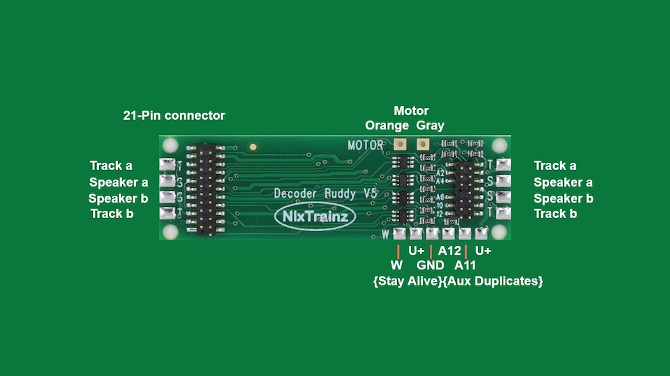
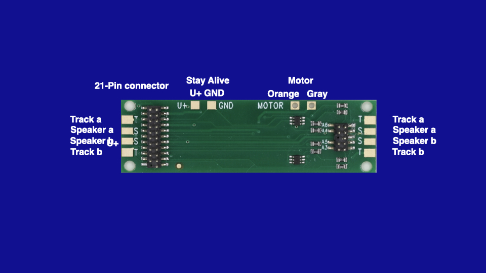
Additional V5 Motherboard Information
The mother board is easier to see in this expanded view (above). On the motherboard the four pads arranged vertically on each end are, from top to bottom, Track, Speaker, Speaker, Track. The Speaker pads are wired in parallel, top to top and bottom to bottom. The two labeled pads across the top are the two MOTOR connections (Orange on the left and Gray on the right). The two motor pads have through holes in the center to allow for wire insertion from the bottom of the printed circuit board for a neater connection. A consistent motor connection color scheme does not seem to exist so these two pads are not labeled as to polarity or color. You should test that the locomotive runs in the correct direction before reinstalling the shell. The five labeled pads across the bottom are U+ {a nominal 14 volts and the place where the stay alive blue (+) wire is attached,} GND is ground for the stay alive. U+ and GND are provided for a stay alive. The NMRA Standards state that the positive pin (U+) of the 21 pin decoder should be connected to the blue wire (+) of the capacitor (stay alive). The 21 pin connectors should fit into the decoder easily. Do not try to force either connector board or decoder onto the pinned headers on the motherboard until pins are correctly positioned. After the pins are aligned properly firmly press the connector board or the decoder onto the motherboard so the pins of the 21 pin connector are flush with the top of the plastic connector on the top of the decoder. If disassembly is required a sharp or narrow object inserted at the end of the connector to move the board a little at a time from each end is effective.
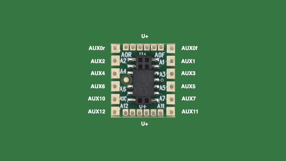
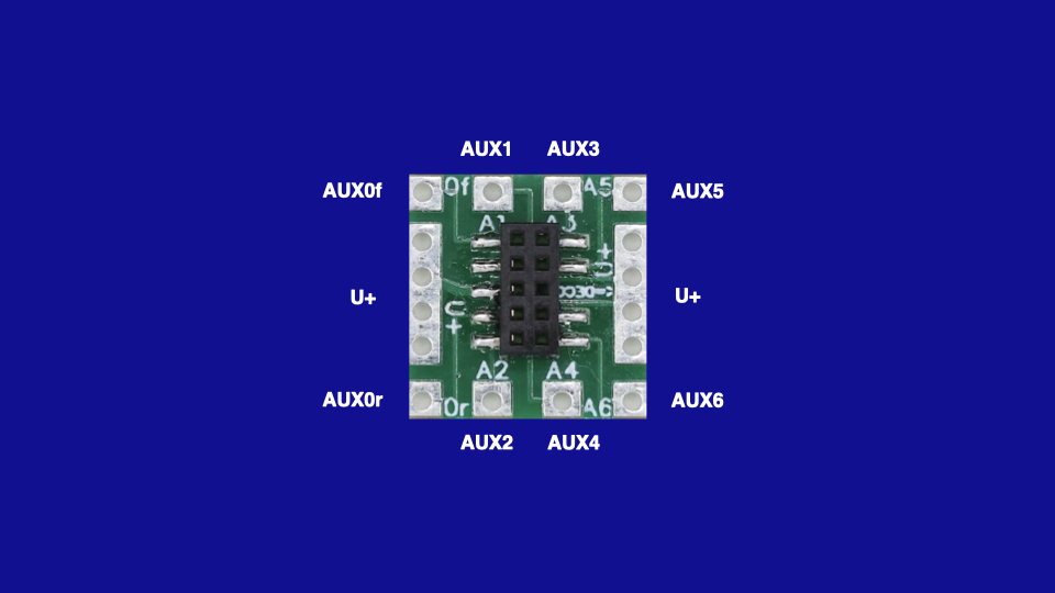
Additional V5 Connector Board Information
The connector board is arranged so the wires from one end of the locomotive are routed though one side of the locomotive and wires from the opposite end are routed through the other side. Function A0f is usually the front headlight and function A0r is usually the rear headlight. A1, A3, A5, A7 and A11 occupy the pads on one side of the connector board. This was done in an attempt to organize the decoder functions and output wires to the front and back of the locomotive. (See the compatibility table for different decoder manufacturer’s pin configuration outputs.) U+, the blue wire (may be the red wire on the LED) are all common are all connected to the six small pads on each end. These are all connected within the connector board. Note that when the direction of the large gold dot is on the side toward the 21 pin decoder the keyed 14 pin connector will mate properly. The connector board and the pinned header on the motherboard should fit together easily. Do not try to force either connector board or decoder onto the headers on the motherboard until pins correctly positioned. After the pins are aligned properly firmly press the connector board or the decoder onto the motherboard so there is no space between the header and the printed circuit board. In some installations it may be possible to separate the connector board from the motherboard before removing the locomotive shell. This makes the process of separating the frame and motor parts from the lights in the shell less cumbersome.
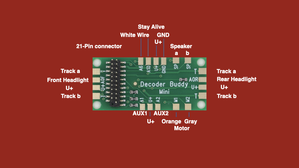
Additional Mini Motherboard Information
It is important to note that the A6 and A10 pads are logic voltage, 5 volts. These are provided to control a Power Pack, smoke unit, servo or whatever. They are low voltage, low current outputs. There are only four (lighting) function outputs on the motherboard.
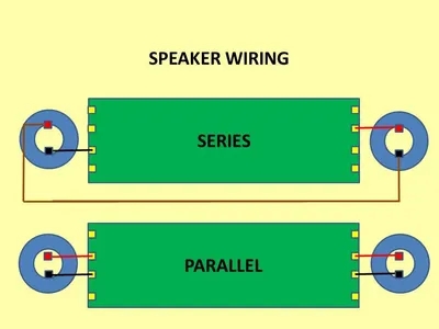
Two or more speakers
can be wired to the Decoder Buddy.